
Shop Now
-
Hydraulics
- Parts
- Fittings
- Motors
- Filters
- Hose Tails
-
Adaptors
- Tube Weld
- Caps
-
Straight
-
Nipple
- BSPP Male x BSPP Male
- BSPP Male x JIC Male
- BSPT Male x BSPT Male
- BSPT Male x JIC Male
- BSPT Male x UNO Male
- JIC Male x JIC Male
- NPT Male x NPT Male
- ORFS Male x Metric Stud Male
- ORFS Female x ORFS Male
- NPT Male x NPT Female
- BSPT Male x MS Male
- BSPP Male x UNO Male
- BSPT Male x BSPP Male
- BSPT Male x NPT Male
- NPT Male x JIC Male
- JIC Male x ORFS Female
- JIC Male x UNO Male
- JIC Male x ORFS Male
- JIC Male x Metric Stud Male
- UNO Male x ORFS Male
- ORFS Male x ORFS Male
- JIC Male x JIC Female
- BSPP Female x JIC Male
- BSPT Male x ORFS Male
- BSPT Male x ORFS Female
- Metric Stud Male x Metric L Ma
- ORFS Male x ORFS Fixed Female
- JIC Male x Code 62
- Metric L Male x Metric L Male
- Reducing Bush
- Socket
- Bulkhead
- BSPT Male Suction Tail
- UNO Male Suction Tail
-
Male x Female Swivel
- BSPP Male x BSPP Female
- BSPP Male x JIC Female
- BSPP Male x ORFS Male
- BSPT Male x BSPP Female
- JIC Female x ORFS Male
- BSPP Female x UNO Male
- JIC Female x UNO Male
- BSPT Male x JIC Female
- ORFS Fixed Female x ORFS Male
- JIC Male x JIC Female Restr
- BSPP Male x ORFS Female
- JIC Male x BSPP Female
- JIC Male x JIC Female
- BSPP Male x Metric H Female
- BSPT Female x BSPP Male
- BSPP Male x Metric L Male
- BSPP Male x Metric L Female
- BSPP Male x Metric H Male
- BSPT Female x BSPT Male
- OEM Female x BSPP Male
- Male x Female Solid
-
Nipple
- Plug
- Tee Piece
- Cross
- Flange Clamps
- Banjo Bolts
- Tube Fittings
- 45 Degree Elbow
-
90 Degree Elbow
-
Elbow Block
- BSPP Male x JIC Male
- BSPT Male x JIC Male
- BSPP Male x ORFS Male
- BSPT Male x BSPP Female
- Metric L Male x Metric L Femal
- NPT Male x NPT Female
- JIC Male x Metric Male
- BSPP Female x UNO Male
- JIC Male x UNO Male
- BSPT Female x BSPT Female
- BSPP Male x BSPP Female
- BSPP Male x BSPP Male
- BSPT Male x BSPT Female
- BSPT Male x BSPP Male
- BSPT Male x UNO Male
- BSPT Male x BSPT Male
- BSPT Male x Suction tail
- NPT Male x JIC Male
- JIC Male x JIC Female
- JIC Male x ORFS Female
- JIC Male x JIC Male
- UNO Male x ORFS Male
- UNO Male x Suction Tail
- ORFS Male x ORFS Male
- NPT Male x ORFS Female
- ORFS Female x ORFS Male
- Elbow Tube
- Bulkhead
-
Elbow Block
- Hose
- Valves
- Pumps
- Cylinders
- Power packs
- Breakaway Couplings
- Pipe Clamps
- Seals
- Ferrules
- Equipment
- Hydraulic Hose Kits
- Misc
Blog Archives
Blog Categories
Upcoming Events
Just Arrived
What's New
Follow Us
Latest Posts
Overcenter Valves are Key to Hydraulic Control
Often used as braking valves, these components keep HSTs from overrunning.
Traditional hydraulic valves are being ousted in favor of sleeker, lighter, and hardier cartridge valves. With the ability to be mounted straight into machined manifolds that internally connect the valves rather than external piping as in the case of traditional valves, these hydraulic integrated circuits (HICs) eliminate unnecessary tubes, hoses, and fittings. As each fitting provides two potential leakage points, the basic principles of hydraulic machinery operations are upheld to a higher standard.
As with the many options with traditional parts-in-body type valves, cartridge valves manifest themselves in a myriad of forms, from the humble check valve to the state-of-the-art proportional solenoid direction control valves.
The lifeguard, however, for any hydraulic actuator, is the over-center valve. This motion controlling marvel is the successor of the counterbalance valve. The name counterbalance came from the counterbalancing weights used in the earlier machine tools to prevent the ball screw from coming under heavy load. These valves were designed in the early thirties by Harry Vickers’ team, who developed them as spool-type valves and hence were not found to be zero leaks.
While counterbalance valves maintain a healthy amount of backpressure, they force the pump to develop the full set pressure on the counterbalance spring before they allow the actuator to move. As shown in Figure 1, a counterbalance valve attached to the full-bore (cap end) area of the cylinder and set to 150 bar, at zero load, will force the pump to develop a pressure of 300 bar at the annular (rod end) area before the cylinder is allowed to move (if the annular area is half the full bore).
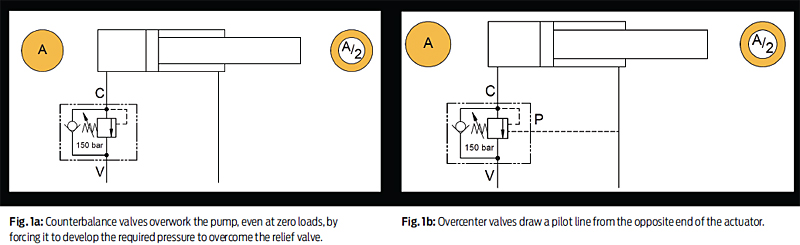
In turn, what the over-center valve does is use a pilot assist from the opposite end of the actuator to move the poppet against the spring. An over-center valve can be described as a pilot-assisted relief valve with an integral free flow check. The performance of over-center valves are at best when mounted into the actuator, whether it is a linear (cylinder) or a rotary (hydraulic motor) actuator. However, if not, they should be connected to the actuators with rigid piping.
The disparity between a pilot-operated check valve and a pilot-assisted relief valve must be noted here. While a pilot-operated check valve opens fully as soon as the pilot port develops a pressure that is sufficient to open the poppet, in the case of the over-center valve, the pilot pressure has to overcome a strong spring. The spring’s force is reduced by the simultaneous action of pressure on the cylinder port due to the weight of the load. In short, in pilot-operated check valves, the pilot pressure and load pressure act against each other, while in pilot-assisted relief valves, they act in the same direction against the spring. This opens the poppet gradually and causes the flow to the meter.
Overcenter valves were used mainly for the following purposes:
Load holding: The over-center valve prevents the movement of a load when the directional valve is in the neutral position, permitting the use of open center directional valves and negating leakage past the spool of closed center directional valves.
Load control: The over-center valve prevents the actuator from running ahead of the pump due to the load-induced energy, thereby eliminating cavitation in the actuator and loss of control.
Load safety: In the case of hose failure, an over-center valve mounted onto or into a cylinder will prevent uncontrolled movement of the load. When a cylinder is used in a boom, as in a crane, then hose failure protection is vital as the loss of load control could cause damage to people or property.
Relief setting of the over-center valve for most applications is a matter of common sense and judgment. In the case where the load varies drastically and sudden impact loads are expected, the relief pressure could be 20-30% more than the load pressure. However, for horizontal cylinders, this could be as low as 5-10%. This ensures that with the maximum load on the actuator the valve will remain closed until pilot pressure is applied. The pilot pressure required to open the valve will depend on the pilot ratio that is the ratio between the relief area and the pilot area. The pilot pressure can be calculated as follows:
Pilot pressure = valve setting – load pressure / pilot ratio
Figure 2 shows the pressure drop curves of two valves with different pilot ratios. The higher pilot ratio valve is more restrictive than the low pilot ratio valve. This shows that above a certain pressure, the lower pilot ratio valve is more efficient than the higher pilot ratio valve. It is important that the total performance is taken into account before specifying an over-center valve.

Fig. 2: Relationship between flow and pilot ratio. Above a certain pressure, the lower pilot ratio valve is more efficient than the higher pilot ratio valve.
To explain the need for over-center valves, the perfect example would be an inverse pendulum, as shown in Figure 3. Here, a cylinder is attached to a pendulum which has a load at its end. The cylinder’s retraction and extension help the pendulum sway backward and forward. To push the pendulum from one extremity to another during its ascent, the cylinder acts against the load and the force of gravity—hence the pendulum is always in control with the pump driving the load.
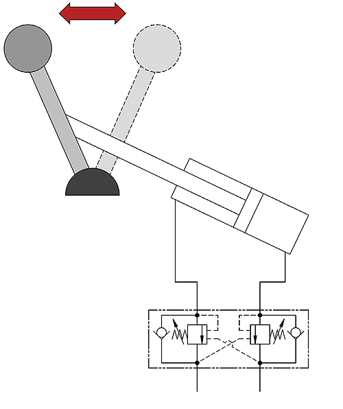
Fig. 3: The hypothetical inverted pendulum is the best example for the need for an over-center valve.
As the pendulum goes over its center of gravity and starts its descent, the load becomes unbalanced, with the pendulum trying to move faster than the cylinder will allow it to. Now the load ends up driving the pump since the load and gravity are acting in the same direction as the cylinder. Here the over-center valve would regulate the movement of the cylinder by metering the flow out of it and subsequently keeping the load in control at all times.

Fig. 4: Overcenter valves should never be connected to blocked center directional control valves. If there is a sudden switch to the block center (1) or a pressure spike due to the temperature rise of the fluid (2), the fluid has no place to escape and can end up bursting hoses, damaging equipment or even putting operator’s lives at risk.
Since the scenario is repeated in the reverse direction, a second over-center valve is required for the same reason on the opposite line. In this case, a dual over-center valve is used, which regulates the flow out of a cylinder at both ends.
Dual over-center valves also find use in track wheels of large earth-moving equipment (Figure 5), where the machines are required to climb steep inclines. Equipment needs to be able to move both forward and in reverse on steep slopes. Moving forward on a descending slope and reversing on an ascending slope, the machine tends to roll forward or backward respectively. Dual over-center valves connected to the hydraulic motors keep the load from running away by controlling the outward flow of oil in both directions. However, a parking brake is a must for rotary actuators.
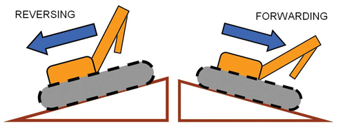
Fig. 5: There are cases where mobile equipment on an incline may go out of control, due to inadequate control of the track wheels. Reversing on inclines and forwarding on slopes result in the load running away.
Overcenter valves are also used on hydraulic motors in applications such as winches, as elaborated in Figure 6. Reeling in the winch while lifting the load happens against the force of gravity, which results in the pump driving the load. While lowering, however, the load and gravity act in the same direction. This results in the load running away and a possible loss of control. Here the over-center valve meters the flow out of the hydraulic motor to keep the load in place.

Fig. 6: Winches inherently require over-center valves to prevent load runaway while lowering the load. This however is not a fail-safe method to hold the load in place. A parking brake should be installed to protect the load from falling catastrophically.
Overcenter valves are typically mounted on the cap of a linear actuator or they can be line mounted with rigid piping between the actuator and the valve. The cylinder port of the valve is connected to one end of the actuator while the valve port is connected to the directional control valve. The pilot port is connected to the opposite end of the actuator.
In Figure 7, the cylinder has to be extended against the weight of the load—the oil flows to the cap end over the check valve extending the piston, while the opposite end is drained of oil. For retraction, the over-center valve restricts the flow of oil out of the cap end, resulting in the pressure rising at the opposite end. This pressure is sensed at the pilot port of the over-center valve, which, assisted by the load-induced pressure, compresses the spring giving an outlet to the oil from the cap end.

Fig. 7: Operating an over-center valve with a linear actuator.
If the load were to run away, the flow out of the cap end would increase starving the rod end of oil, resulting in a drop in pressure. Consequently, the pilot pressure would no longer be high enough to keep the spring compressed. This shuts off the flow moving out of the cylinder. In this way, the load and its movement would be back under control by continuously metering the flow out of the cylinder.
As with any hydraulic valve, there is always a functional variety. The same goes for the over-center. The valves come in two types of relief designs. One is a direct-acting relief valve which features quick response and zero leak characteristic. The other is a differential area over-center, which gives a higher flow capacity (>300 lpm) but with a poor reseating characteristic.
Overcenter valves used in conjunction with proportional valves are required to be fully balanced and will allow the downstream pressure to be high without affecting the relief spring setting.
A note of caution: saying that the Overcenter valve is a load holding valve, is true only in the purview of linear actuators (cylinders). This is because of the inherent leakages within the motor—the rotor of the motor will always have leakages from the high pressure to the low-pressure zone.
For controlling a rotary actuator, a parking brake engaged with the help of a shuttle valve, a spring-loaded cylinder and perhaps a pressure reducing valve is mandatory. Pressure in any of the lines will be sensed by the shuttle valve, keeping the parking brake disengaged. When the pressure in both the lines is zero (when the valve is in the neutral position), the pressure stops holding back the spring in the cylinder of the parking brake and engages it with the hydraulic motor, stopping its motion.
Another point of care is that over-center valves should never be connected to directional control valves with a blocked center spool. The neutral position of the valve should always be of a float center configuration. This reduces the pilot pressure to zero in the neutral position, ensuring that the piston reseats correctly. This also means that the valve can function as thermal relief and can even eliminate unwanted pressure in the cylinder port
Credit: Design World